Doc Race Intake Manifold Install Guide & Dyno Results – BMW 135i & 335i (N54)
If you’re a diehard N54 enthusiast, you know that there are very few aftermarket intake manifolds available for us. Lucky for us, the Doc Race Intake Manifold is a great option!
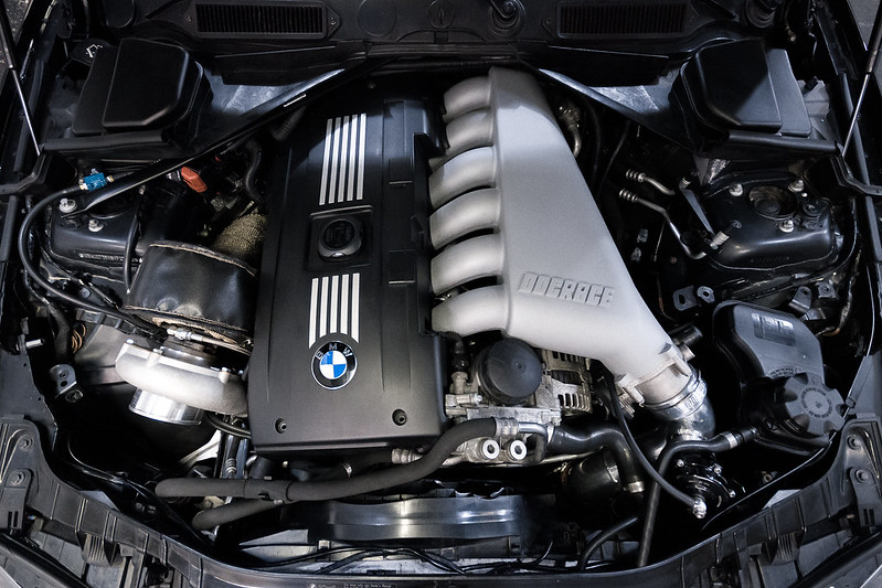
I had to get one to match my Doc Race N54 single turbo kit. One of the reasons I wanted this intake manifold was because it integrates port injectors directly into the manifold. The typical N54 port injection method (which I currently have) involves a spacer between the engine and stock intake manifold that creates an additional surface for potential boost leaks. Not only that, but it looks awesome too!
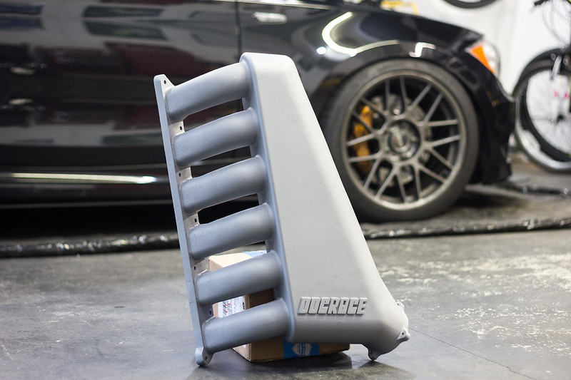
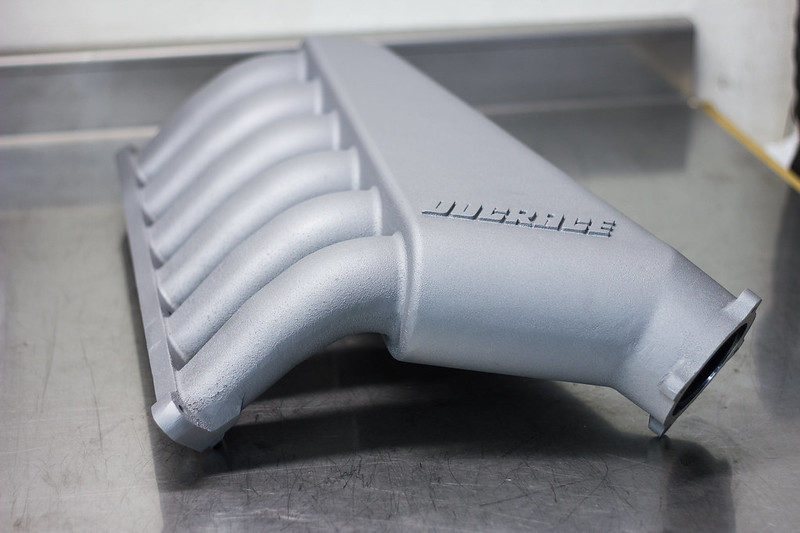
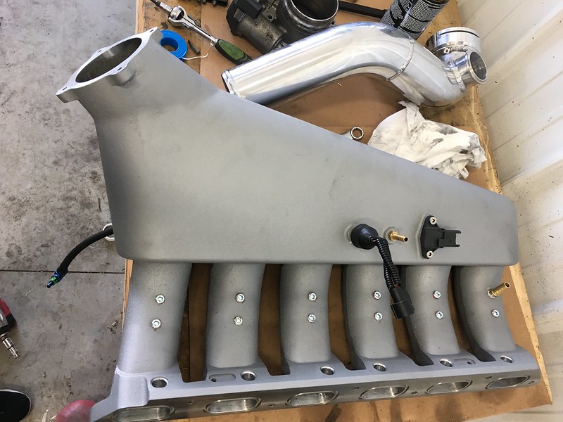
The Doc Race intake manifold is cast aluminum and comes powdercoated in your choice of silver, black, blue or red. It has two 1/8″ NPT ports and a provision for the OEM TMAP sensor on the bottom. It also has an additional two 1/8″ NPT ports per runner for meth and nitrous if you like to party.
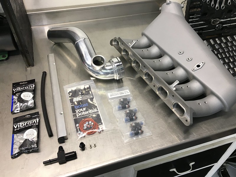
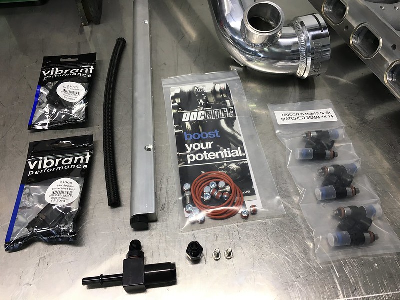
I ordered the package that includes port injection (with 72lb injectors) and a 3″ charge pipe. As you can see, it comes with the following:
- Fuel rail (raw finish)
- Fuel hose and Vibrant AN fittings (requires assembly)
- T-fitting for fuel supply
- Fuel rail mounting brackets
- Stainless hardware to mount fuel rail and manifold TMAP sensor
- (6) 72lb/750cc fuel injectors
- (6) intake runner gaskets
- (14) 1/8″ NPT plugs with thread locker
- 3″ charge pipe with TiAL blow off valve flange
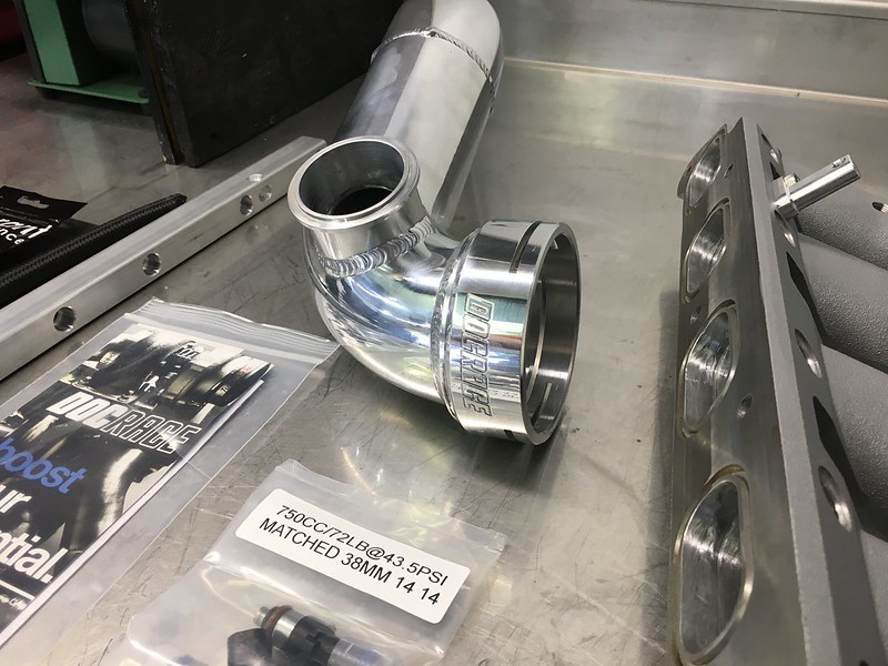
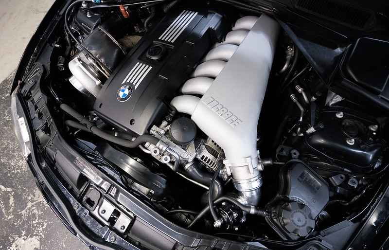
My overall impression of everything was good. The manifold finish is noticeably cast, but this was expected. The polished chargepipe is beautiful with very clean welds. I couldn’t wait to replace the ugly stock manifold with this piece of art!
First step was to clean all of the pieces. John included a note that warned to thoroughly inspect all parts for metal burs and to clean out any machining debris. I imagine that since we’ve been rushing him to get these manifolds out the door, he put this responsibility on the customer and I’m okay with that. I did find a few burs that I smoothed out and metal flakes that I rinsed out. No big deal.
Next up was a mental inventory on additional parts I’d need to order to complete this installation. I went through the installation in my head and came up with the following list of parts to buy.
- 1/8″ NPT to 1/4″ barb fitting for BOV connection
- 1/4″ vacuum line to reach further BOV connection
- 3/8″ fuel hose to extend EVAP hose
- 20ga wire to extend throttle body and TMAP harnesses
- 20ga weatherproof crimp connectors
- 3 inch 45 degree coupler for VRSF 7.5″ intercooler connection
- Throttle body gasket
- Teflon tape
- Zip ties
- Wire stripper/crimper
- E90 328i power steering bracket
- TiAL Q Series blow off valve (if you got the Doc Race charge pipe)
- Optional: 3/8″ split loom to group and hide the extended wiring
- Optional: 1/8″ NPT to 3/8″ barb fitting to relocate EVAP hose
- Optional: 3/4″ vacuum bypass cap to relocate EVAP hose
- *if you have 335D coolant reservoir, you will need to replace or reposition it for the manifold to fit!
Once I received everything, I drove to Lindgren Supercars and got to work! Since I already had port injection, I was familiar with removing the factory intake manifold. If you can’t figure out how to remove it, you might want to leave this job to a professional.
After removing the stock intake and my VRSF charge piping, I swapped over my Hobb’s switch and TMAP sensors (3.5 bar to charge pipe, OEM to manifold). I installed the 1/4″ barb fitting next to the Hobb’s switch. Since I’m not using meth or nitrous, I installed the 3/8″ barb fitting in one of the available ports on the 6th runner. This is where I’ll be relocating my EVAP line to, so I don’t have to run it all the way to the throttle body. That’d be ugly anyways. I proceeded to plug the rest of the meth/nitrous ports with the plugs.
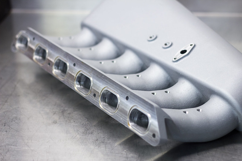
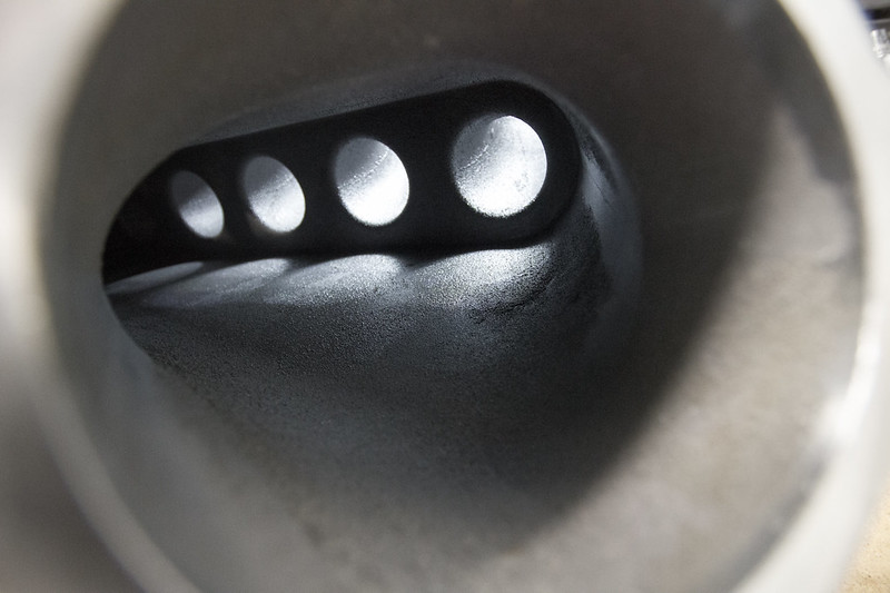
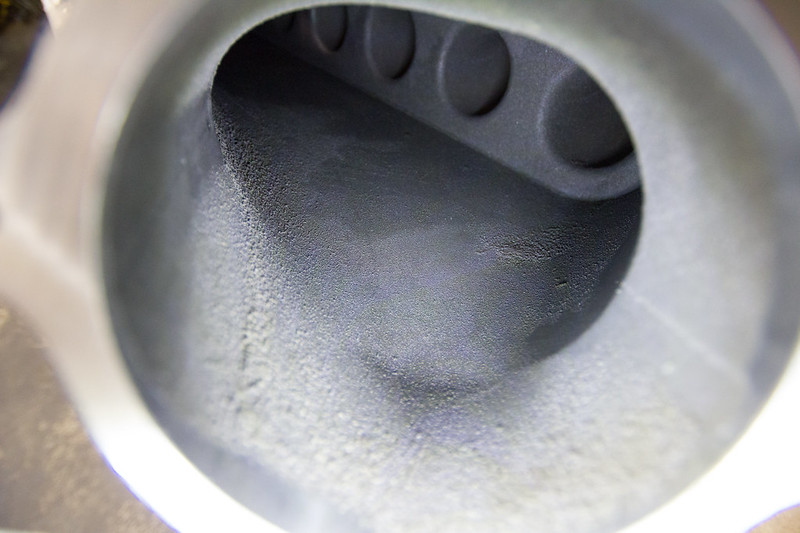
You can see in the photo above that the fuel injector ports are not centered in the middle of the port. While this might bother some people, I doubt it will be an issue. The first cylinder port is offset on every port injection kit on the market.
If you opted for the manifold without the port injection kit, you will install the injector block-off plate instead. If you got the manifold with port injection but don’t have it previously installed like I already did, you will need an external controller (JB4 or AIC6). You’ll have to follow a separate DIY for that depending on the route you go.

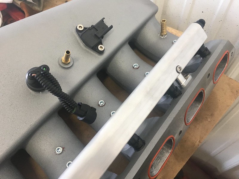
Next, I installed the throttle body, manifold o-rings, and fuel rail.
NOTE: The fuel rail IS directional. I have it installed backwards in the photo above. You will notice one side of the rail is longer than the other (more space between the injector and the end of the rail). The longer side needs to be installed towards rear of the car. You can see I had the long side towards the throttle body, but it will interfere with the oil filter housing if you install it this way. The two brackets will have to be flipped and you will have to tighten the rail down from the top side of the manifold.
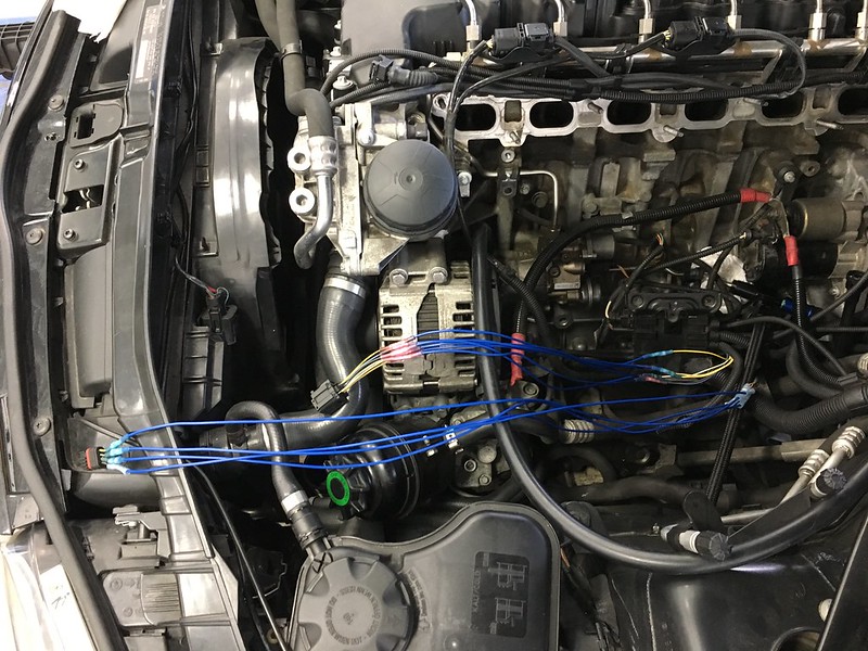
Before installing the manifold, I extended the 6 wires from the throttle body sensor about 1.5ft and the 4 wires from the charge pipe TMAP sensor about 3ft. Better too long than too short. I simply cut the plugs off, then used weather proof crimp connectors on both ends to extend the harnesses. Pay attention to the colors and match them up accordingly. You will need to reuse your TMAP adapter harness if you have an upgraded TMAP sensor.
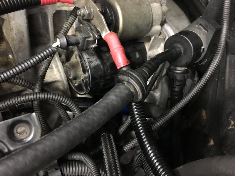
At this point, I assembled the fuel line and Vibrant AN fittings that came from Doc Race after watching this how-to video. Then I installed that fuel line with the T-fitting that connects between the car’s fuel feed line and the HPFP. If you look closely, you can see the fitting and hose installed in the photo above. Be sure to disconnect the battery when working with fuel lines.
Next up, I heated up the EVAP hose and removed the piece of plastic hose that previously attached to the throttle body. In place, I installed ~1ft of the 3/8″ fuel line I purchased. This will connect to the 3/8″ barb fitting I installed in the 6th runner. Check for kinks once installed and be sure to zip tie this connection so it doesn’t pop off under pressure (ask me how I know).
If you’re not relocating the EVAP line and want to run it to the factory connection on the throttle body, you just need to extend this line and reattach the OEM fitting. Be sure to clock the throttle body so you can easily connect it. See photo below, before I added a zip tie to secure the hose.
Now we’re ready to wiggle this manifold on. It’s a very tight fit and helps to have a second set of hands. If you have port injection, connect and tighten all fuel and electrical connections before bolting the manifold down. Once you’ve positioned the manifold onto the studs, you can connect the rest of the accessories (Hobb’s switch, vacuum lines, EVAP hose, TMAP and TB plugs, etc).
Make sure none of the orange o-rings popped out of their place. You’ll have to get creative to torque the manifold down because of the angle of the runners. You can’t get direct access to the nuts on each stud. I used a deep socket with a swivel and an extension.
Time to get that charge pipe in there. It’s easiest to install without the blow off valve attached. Oh, and don’t forget to transfer over the large o-ring inside the charge pipe near the throttle body connection before installing it. Finagle it in place and connect it to your intercooler. Since I previously had a VRSF charge pipe and their 2.5″ lower hard pipe, I had to order a new 3″ coupler to fit the larger Doc Race charge pipe. In my case, I actually had to shorten the bottom of the charge pipe in order to connect to my VRSF 7.5″ intercooler. Each intercooler might require a different pipe length and coupler size and/or angle.
Once you get the charge pipe mounted, insert the c-clip and push the pipe onto the throttle body until it clicks into place. Then you can install your TiAL blow off valve. Carefully route the coolant expansion tank hose so that it isn’t pinched or kinked against the BOV. You might have to extend it if it’s too tight, like mine was.
I hid my oil catch can and power steering reservoir under the manifold. I might relocate my power steering reservoir to the strut tower after reading that an E90 328i bracket will work. The coolant reservoir mounts might need to be adjusted as well.
Plumb your BOV vacuum line to the bottom of the manifold. Install your rubber bypass cap onto the old EVAP bung on the throttle body if you relocated it like I did. Check that all vacuum/EVAP lines have a zip tie holding them tight. Go over all your hoses and lines to verify that none are pinched or kinked. Plug in all sensors and electrical connections. Connect the battery and turn the key on to prime the fuel pump. Check for fluid or fuel leaks. If everything seems kosher, start the car. Listen for vacuum leaks or whistling noises.
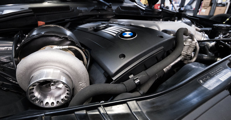
At this point, admire your newest addition to your engine bay. If you have port injection, go for a short drive and make sure you see a PI trace in your logs. It’s important to verify that the port injectors are functioning properly and that your AFRs are in check.
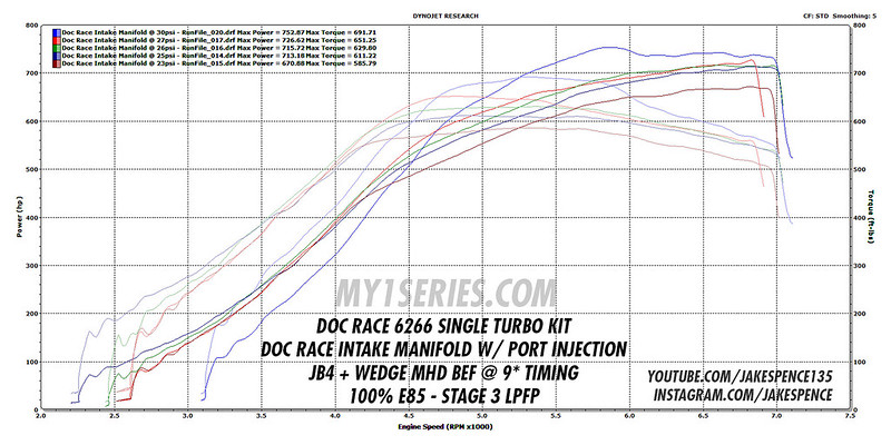
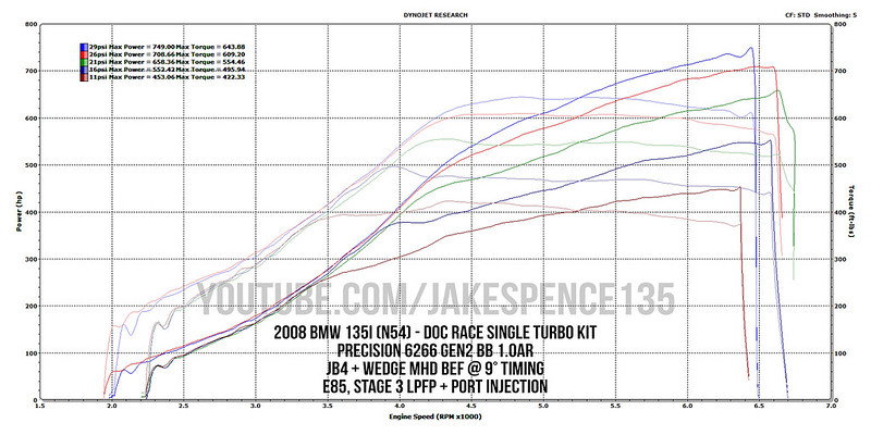
If you’re like me, you probably want to know what kind of performance difference this manifold makes. I immediately strapped the car on the dyno to get some results!
Doc Race Intake Manifold Results:
- Run conditions: 90°F with 41% humidity (8/11/18)
- 30psi: 752whp / 691wtq
- 27psi: 726whp / 651wtq
- 26psi: 715whp / 629wtq (+7whp / +20wtq!)
- 25psi: 713whp / 611wtq
- 23psi: 670whp / 585wtq
Doc Race intake vs. stock intake (two months earlier):
- Ambient temperature difference of +12°F (favors stock manifold)
- Starting point difference of 1200 RPMs (favors stock manifold)
- Boost difference of 1psi (favors Doc Race manifold)
-
RESULTS: +49whp and +47wtq at 5500 RPMs!
- Doc Race manifold picks up solid power in the midrange
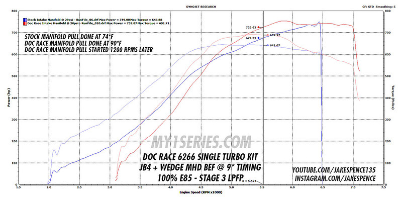
BEFORE (two months earlier) – Stock Intake Manifold Results:
- Run conditions: 74°F with 48% humidity (6/3/18)
- 29psi: 749whp / 643wtq
- 26psi: 708whp / 609wtq
- 21psi: 658whp / 554wtq
I couldn’t get an exact apples-to-apples comparison. Obviously the temperature was not in favor of the Doc Race manifold, but it still did well!
The “before” (stock manifold) dyno runs began at 2K RPMs while the “after” pulls began between 2500-3K RPMs, making the Doc Race intake manifold look laggier, but that’s not the case. My final 30psi pull was started noticeably later, giving the turbo even less time to spool up.
Either way, the manifold picks up noticeable torque! I hope to go back on a cool morning (~72°F) to get a more apples-to-apples comparison where I can start the runs at the same RPM. This will also give the car ample time to adapt to the new intake manifold.
Overall, I’m happy with the upgrade. A bump in power and less connections for potential boost leaks. This manifold does get hot, but that can be addressed with a phenolic spacer. I’m not sure how much of a difference it would make for performance, but I didn’t want to recreate the potential spacer leaking situation that I just got away from.
I should note that the manifold does sit close to the oil filter cap. The clearance might improve if you were to install a phenolic spacer, I’m not sure. The manifold does not touch or interfere with the oil filter cap, but I was unable to slip my standard oil filter cap wrench on anymore. I used this pair of adjustable oil filter pliers to remove the oil filter without an issue. It loosened and removed easily. Phew.
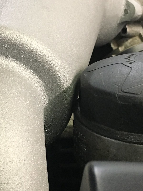
I am going to get this billet oil filter cap that should allow me to remove the oil filter more easily in the future. Plus, it looks better.
This page contains affiliate links. If you purchase anything using the links above, I will earn a small commission at no extra cost to you. Win-win!
Awesome write up, I am doing mine next week! what did you do with the brake pressure line?
Looks like I didn’t include that in the write up because I previously modified it. You can use the same 3/8″ hose or vacuum line to eliminate the hardline.
What did you do with your brake boost line? I am doing my manifold this weekend and stealing these ideas. Great write up!
Sorry I didn’t reply sooner! I just saw these comments. As I replied before, you can use the same 3/8″ hose or vacuum line to eliminate the hardline.
Will this fit on the N55?!?!!
No, it will not. It does not have the provision for the N55 DME.
Great DIY, it helped me immensely. I just did the install this evening, the 45 coupler did not work for me. I had to order a 90. All cars are going to be different as you had mentioned in the post. Can’t wait to fire it up when the 90 comes!
Awesome, glad you found it helpful! The intercooler coupler can be tricky, I’m excited for you once you get it connected!
Great write up! Just wondering, are you running a return line and external fuel pressure regulator with your Stage 3 LPFP?
Hi Nick – no I am not.